Adam J. LaDine
New England Biomedical Engineering Professional
DCFD Drawing Improvements
This is an overview of a new drawing style that I developed for the management of single-use parts in process engineering.
Shire Pharmaceuticals in Lexington, Massachusetts makes heavy use of single-use technology in their manufacturing operations. To manage single-use parts, they use Disposable Component Flow Diagrams (DCFDs), a type of Process Flow Diagram that specifically identifies where single-use parts are located in the process equipment.
DCFDs are created per process step, not per equipment. If redundant equipment is present, the DCFD applies to any of the redundant options that are validated for use in that process step.
During my time at Shire, I was able to develop an improvement to Shire’s DCFDs that was ultimately codified in their SOPs.
In a DCFD, single-use parts are identified by a number in a diamond. The drawing is accompanied by a table of parts, organized by “diamond number”, listing out all single-use parts approved for that point in the process.
Here is a DCFD drawing snippet of a wave bioreactor, used in upstream cell culture:
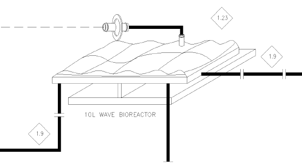
To find the parts approved for use as a 10L wave bag bioreactor, the reader would look up part 1.23 in the corresponding table. Similarly, to find the tubing used at the inlet and outlet of the wave bag, the reader would look up part 1.9.
Note the use of block arrows to indicate boundaries between parts. Since bioreactor bag 1.13 includes tubing stems, the block arrows clearly indicate that tubing 1.9 does not extend all the way to the bag itself. Additionally, the ports on the wave bag are placed in their actual position.
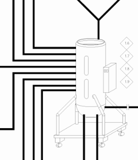
In this snippet, it is not clear which parts are intended to be identified by the diamonds 1.6, 1.7, 1.8, and 1.9. Furthermore, the lines that are drawn connecting in the back actually connect on top, and the one line coming out the top actually goes on the bottom.
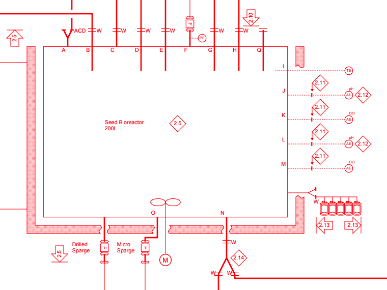
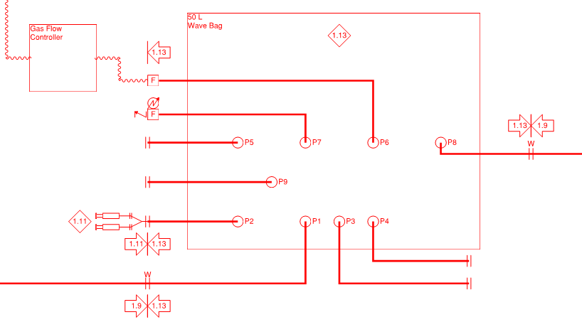
As with my redrawn wave bag, my redrawn upright bioreactor shows the connections drawn in a way that reflects the real-world configuration of the equipment. Functions of tagged parts are immediately apparent without having to consult the parts table. I even included some P&ID notation for the disposable sensors to improve readability.
These stylistic and symbolism changes were positively received by the relevant SMEs. They recognized the value and time efficiency generated by the cleaner and more informative drawing style, and an SOP change was approved to allow for my new style of DCFD.
Upon contacting a former colleague about 10 months after leaving Shire, I was told that others have begun using my style of drawing in their own work.